DESIGN PRIORITIES IN EV TRACTION INVERTER WITH OPTIMUM
PV inverter loop design
This report presents a detailed simulation of a solar photovoltaic (PV) inverter system using PSIM software. The system includes six PV panels, a DC-DC boost converter, an inverter bridge, and a closed-loop control circuit. [pdf]
Solar inverter design
Designing a solar inverter circuit essentially requires two parameters to be configured correctly, namely the inverter circuit and the solar panel specs. The following tutorial explains the details thoroughly. . A buck converter will effectively convert the excessvoltage from your solar panel into an equivalent amount of current (amps) ensuring an optimal output/input = 1 ratio. There are a. . In the previous section I have explained to design a solar inverter using a buck converter for inverters with lower battery voltage rating than the panel and which are intended to be. . All the designs which are so far discussed are intended to produce a squarewave output, however for some application a square wave could be undesirable and might require an. [pdf]FAQS about Solar inverter design
How do I design a solar inverter?
Designing a solar inverter can be a complex process that involves a good understanding of electronics, power systems, and solar energy. Here are some general steps to consider when designing a solar inverter: Determine the load requirements: The first step in designing a solar inverter is to determine the load requirements.
What is a solar inverter?
A solar inverter is a device used to convert the direct current (DC) output of an array of photovoltaic cells into alternating current (AC). It forms part of a larger system that includes the solar panel, battery and charge controller. There are many benefits to using a solar inverter in any energy-producing application. Cost Savings
How does a solar inverter work?
The output voltage from the solar panel is immediately supplied into the LM317 positive regulator circuit, which is regulated to produce 12 volts. The battery is wired to this bias by a Schottky diode. The CD4047IC integrated Circuit is connected and set up as an astable multivibrator in this solar inverter circuit.
Which solar inverter should I use?
Contemporary solar applications require very highly efficient, power-dense and lightweight grid-tied inverters. Traditionally, IGBT has been the device of choice in both three-phase and single-phase (≤10 kW) solar inverter designs while superjunction (SJ) MOSFETs (600/650 V) also have been used in some single-phase designs.
What is a solar PV design & installation guide?
This is a the third installment in a three-part series on residential solar PV design. The goal is to provide a solid foundation for new system designers and installers. This section is dedicated to the basics of inverter sizing, string sizing and conductor sizing. Download the full PDF “Solar PV Design and Installation Guide”
What are the different types of solar inverters?
The most common type of solar inverters are string-inverters, which are connected in series to multiple PV modules and provide AC electricity at one central location. Solar inverters also include microinverters, which attach directly to each individual module and convert DC electricity from one panel into AC for use onsite. II.

12 volt inverter design
The circuit of a simple 100 watt inverter discussed in this article can be considered as the most efficient, reliable, easy to build and powerful inverter design. It will convert any 12V to 220V effectively using minimum components . An inverter which uses minimum number of components for converting a 12 V DC to 230 V AC is called a simple inverter. A 12 V lead acid battery is the most standard form of battery which. . The article deals with the construction detailsof a mini inverter. Read to know regrading the construction procedure of a basic inverter which can provide reasonably good. . As shown above a simple yet useful little inverter can be built using just a single IC 4047. The IC 4047 is a versatile single IC oscillator, which will produce precise ON/OFF periods. . To begin with, first make sure to have proper heatsinks for the two 2N3055 transistors. It can be fabricated in the following manner: 1. Cut two sheets of aluminum of 6/4. [pdf]FAQS about 12 volt inverter design
How to build a 12V inverter circuit?
Building a 12V inverter circuit requires a detailed understanding of the components and their connections. In order to create a well-functioning inverter, a circuit diagram is essential. The circuit diagram acts as a visual representation of how different components are connected to convert the 12V DC input into 220V AC output.
What is a 12V inverter circuit diagram?
In a 12V inverter circuit diagram, there are several components that play important roles in converting DC power to AC power. Each component has its own specific function to ensure the smooth functioning of the inverter.
What is a 12V inverter used for?
This setup allows for the conversion of solar energy into usable AC power for various applications. What is a 12V inverter circuit used for? A 12V inverter circuit is commonly used to convert 12V DC (direct current) power from a battery or another power source into 120V AC (alternating current) power.
What is a 12V DC inverter?
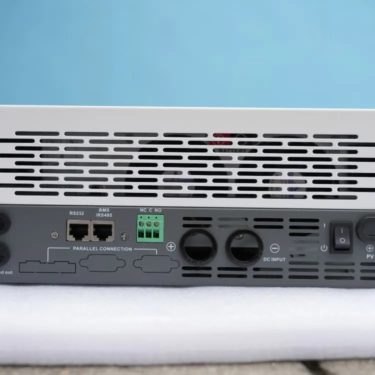
12V DC Power Source: A stable and reliable 12V DC power source is required as the input for the inverter circuit. This can be a battery or an external power supply. DC-DC Converter: A DC-DC converter is used to step up the input voltage from 12V DC to a higher voltage level, typically around 300-400V DC.
How does a 12V to 230V inverter work?
The 12v to 230v inverter circuit works by using electronic components, such as transistors and transformers, to convert the DC input voltage into a high frequency AC voltage. This high frequency AC voltage is then stepped up through a transformer to reach the desired 230 volt output.
How do you connect a 12V inverter?
After assembling the circuit, connect the 12V battery to the input of the circuit. This will provide the required DC power for the inverter. Make sure to secure the connections properly and check for any loose wires. Use appropriate gauge wires to handle the current and minimize voltage drop.