12v inverter closed loop control
Closed Loop Control of a Six Phase Interleaved Bidirectional
Abstract—This paper discusses and implements a control strategy for a six-phase interleaved bidirectional dc-dc converter for a battery system for an HEV/EV application. First, basic

Switched-capacitor-based five-level inverter with closed-loop control
This paper describes a five-level (5-L) inverter interfacing a single-stage tied to the grid to a PV system with a feedback control technique and a lower component count.
Activity: Boost Converters: closed loop operation
Much of this exercise mirrors the Buck Converters: closed loop operation lab. The objective of this activity is to close the loop around the boost converter developed in the open-loop exercise

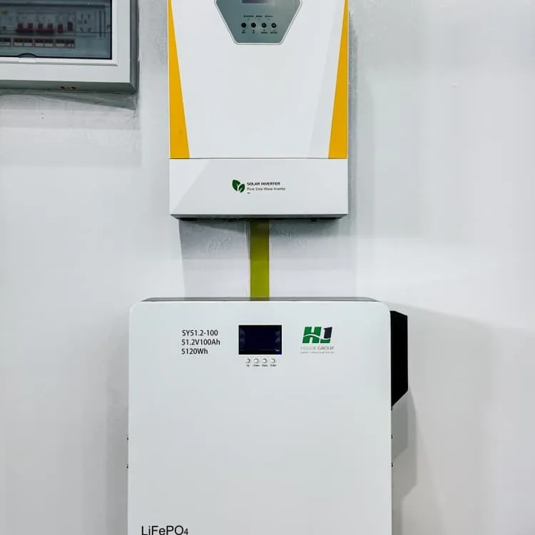
PowMr 3000W 24V Solar Inverter Hybrid 110VAC 80A MPPT
About this item 【Pure Sine Wave】3000W pure sine wave inverter 24VDC to 110V/120VAC, Built-in 80A MPPT charge controller. With full digital voltage and current double closed-loop
Implementation of closed loop control technique for
trategy of the inverter must guarantee its output waveforms to be sinusoidal with fundamental harmonic. For this purpose, close loop current control strategies such as H∞ repetitive

SunGoldPower 10kw with EG4 LifePower4 batteries
I wanted to build a software "Master BMS" which will operate between my six EG4 LifePower4 batteries and my SunGoldPower 10kw inverter. I have discovered that the "Master
Closed Loop operation of Transformer-less Inverter in Voltage
Abstract: A single stage single phase inverter topology derived from Cuk converter, with an input switched inductor, suitable for Photovoltaic-Grid interface is implemented in voltage control

Design and Implementation of Closed Loop Boost Converter
A IMC (Internal Model Control) controller instead of a conventional PID (Proportional, Integral and Derivative) controller has been applied to Boost converter and tested in MATLAB-Simulink

Three-phase inverter closed-loop control based on SVPWM drive
This paper innovatively uses script module programming of plecs software to build the SVPWM modulation module which drive the three-phase inverter while realizing the closed

Closed Loop Control of Three Phase Multilevel Inverter for
Abstract—In this paper harmonic reduction of three phase diode clamped multilevel inverter for grid connected solar system is analyzed. Solar system is controlled and maximum power is
Current Regulated Voltage Source Inverter | CLosed Loop Control
Although Current Regulated Voltage Source Inverter operates as a CSI, it does not use large dc inductor and filter capacitors, hence it has lower weight, volume and cost and faster dynamic
6 FAQs about [12v inverter closed loop control]
How to control an inverter?
trategy of the inverter must guarantee its output waveforms to be sinusoidal with fundamental harmonic. For this purpose, close loop current control strategies such as H∞ repetitive controller, dual closed-loop feedback control, Adaptive Voltage Control, SRFPI controller, Optimal Neural Controlle
Can SVPWM modulation module drive a three-phase inverter?
This paper innovatively uses script module programming of plecs software to build the SVPWM modulation module which drive the three-phase inverter while realizing the closed-loop control. This research will be beneficial to the application of the new driving mode control inverter in practical production. 1.
Does a 5-level inverter raise voltage?
This paper describes a five-level (5-L) inverter interfacing a single-stage tied to the grid to a PV system with a feedback control technique and a lower component count. The inverter will generate a higher voltage at the inverter output, indicating that it can raise the voltage.
What is a multilevel inverter (MLI)?
Multilevel inverters (MLIs) have received a lot of attention in the power sector. The use of MLI to improve the power quality and performance of photovoltaic (PV) systems has increased significantly. The layout, expense, and voltage stress of an MLI connecting PV device are the main MLI constraints that must be optimized.
How does a DC inverter work?
The inverter consists of a boost converter, a switched-capacitor unit, and an H-bridge inverter. The boost converter increases the input voltage to a higher level, and the switched-capacitor unit generates additional voltage levels using capacitors and switches. The H-bridge inverter then converts the DC voltage into AC voltage.
Is MATLAB a good alternative to a linear inverter?
ke MATLAB are considered to be a better alternative to simulate the outcomes of such expensive systems. The proposed closed loop control technique for the inverter working under linear and nonlinear system wil
More industry information
- Dual-transparent solar panels
- How big an inverter should I use for a 7 kilowatt home
- Barbados Battery Energy Storage Frequency Control
- 48v to 12b inverter
- Suriname containerized energy storage system supplier recommendation
- What is the mobile energy storage power supply equipment
- Installation of cabinet-type energy storage system in Bolivia
- Syria Home Frequency Inverter
- Malawi Energy Storage Industrial Park Project
- Photovoltaic plant installing solar panels
- Communication base station European style solar cell 314Ah capacity custom made
- Energy storage project trial operation time
- 9800W all-in-one solar power machine
- Afghanistan new energy storage equipment
- Lithuania energy storage machine price
- El Salvador grid-connected energy storage system manufacturer
- 5 MW of solar energy in Georgia
- Paraguayan battery energy storage system
- A-grade monocrystalline solar inverter
- The DC high voltage before the inverter is lower than the AC
- Modern energy storage module prices in Saudi Arabia
- Price of photovoltaic panels installed on houses in Mozambique
- Tajikistan Enterprise Inverter Recommended Manufacturer
- Bandi Dengdi Photovoltaic Power Generation Project
- Turkish solar panels photovoltaic
- Inverter 2kw sine wave
- High-power battery inverter